Defining Drawing Settings
The Drawing Settings page of the Options dialog box lets you set the behavior of certain drawing commands, the appearance of certain drawing entities, the unit system of the current drawing, manage Custom Coordinate Systems (CCSs), customize the Drawing Scale List, and set up drawing standards verification.
Behavior
To set the behavior of certain drawing commands and set line scale options:
- Do one of the following:
-
Click Tools > Options (or type Options).
Click Application menu > Preferences (or type Options).
In the Options dialog box, click Drawing Settings  .
.
- In the Options dialog box, click Drawing Settings.
- Type DrawingSettings.
- Expand Behavior and select or clear Enable relative dimensions. This specifies that dimensions you create are associated to the measured entities.
- Expand LineStyle Parameters and set:
- Global line scale. Sets a scale factor for displaying LineStyles. This is helpful when zooming in and out.
- Line scale for new entities. Sets the entity line scale for new entities. All entity line scales are displayed based on multiplying the Global line scale by the entity line scale.
- Scale based on sheet's units. Multiplies the Viewport's custom scale by the evaluated value for Line scale for new entities.
- Expand Drawing Boundary and set:
- Enable drawing boundary. Restricts you to drawing entities within the boundary set in Position.
- Position. Sets the drawing boundary borders. Specify the coordinates or click Select in graphics area
 to set the boundaries in the graphics area.
- Expand Entity Frame Control. This allows you to set the frame visibility for Images, OLE objects, PDF and DGN Underlay.
- Do not display and print frame: Hides the frame at the borders of entity in the graphics area and on printouts.
- Display but do not print frame: Shows the frame at the borders of entity in the graphics area, but hides it on printouts.
- Display and print frame: Shows the frame at the borders of entity in the graphics area and on printouts.
- Click OK.
- Click
 .
.
To set display options:
You can control the display of your work area and the appearance of the coordinate system and thumbnail previews.
- Do one of the following:
- Click Tools > Options (or type Options).
- Click Tools > Options (or type Options).
- Click Application menu > Preferences (or type Options).
- In the Options dialog box, click Drawing Settings .
- In the Options dialog box, click Drawing Settings.
- Type DrawingSettings.
- Expand Display and set:
- Show Model and Sheet tabs. Turns on and off the display of the Model and Sheet tabs.
- Show block attributes:
- Normal. Uses the setting defined in the BlockAttribute.
- On. Shows BlockAttributes regardless of the setting defined in the BlockAttribute and regardless if they are hidden.
- Off. Hides BlockAttributes.
- Expand Coordinate System Icon and set:
- Display icon. Displays coordinate system icon in the Model and Sheet tabs.
- Display icon at origin. Always displays coordinate system icon at the origin location in the graphics area.
- Apply changes to all actively displayed views. Applies the settings for Display icon and Display icon at origin to all views.
- Expand Thumbnail and specify when thumbnail previews are updated:
- Model space views. Updates thumbnail previews for Model views.
- Sheet views. Updates thumbnail previews for layout Sheet views.
- Sheets. Updates thumbnail previews for layout Sheets.
- Sheets or views created, modified or restored. Updates thumbnail previews when layout Sheets or views are created, modified, or restored.
- When drawing is saved. Updates thumbnail previews when the drawing is saved.
If you clear all options, thumbnail previews are not updated.
- Click OK.
- Click .
To set the format and size of Point entities:
- See the PointFormat command which opens the corresponding section of the Options dialog box
- In the Options dialog box, click Drawing Settings.
- Expand the Points section.
- In Type, select the display format.
- For Size, type a value.
- Select a size option:
- Absolute units. Point size is set in a value of drawing units.
- % Relative to display. Point size is a percentage of the visible drawing plane.
- Click .
All points in the drawing adopt the new format.
Note: Alternatively, you can use the PointFormat command.
To set up the UnitSystem used in the drawing:
- See the UnitSystem command which opens the corresponding section of the Options dialog box.
To manage CCSs:
- See the CSStyle command which opens the corresponding section of the Options dialog box.
To customize the Drawing Scale List:
To set up Drawing Standards verification for the current drawing:
To set preferences for dimension location snap:
To set preferences for dimension location snap (Professional & Enterprise versions only):
You can force dimension lines to be placed at specified distances from measured linear entities and between successive dimension lines or at specified angles for radius and diameter dimensions.
- Do one of the following:
- Click Tools > Options (or type Options).
- Click Tools > Options (or type Options).
- Click Application menu > Preferences (or type Options).
- In the Options dialog box, click Drawing Settings .
- Type DrawingSettings.
- Expand Dimension snap offset distances.
- Specify whether to Enable offset distances.
- Under Offset distances, set the:
- Offset of the first dimension line from a measured linear entity.
- Offset distance between successive dimension lines.
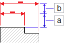
The default offset distances are 0.40 inches (or 10 mm) between the entity and first dimension line and 0.25 inches (or 6 mm) between dimensions.
- In Radial/diameter snap angle, set the snap angle intervals to use when you drag radius and diameter dimensions along radial locations. The default snap angle is 15°.
To set preferences for Centerlines:
To set preferences for Centerlines (Professional & Enterprise versions only):
- Do one of the following:
-
Click Tools > Options (or type Options).
Click Tools > Options (or type Options).
Click Application menu > Preferences (or type Options).
In the Options dialog box, click Drawing Settings .
- Type DrawingSettings.
- Expand Centerlines.
- In Extension, specify the extension for Centerlines to exceed the entities which define the contour.
- Select Keep extension constant in Viewports to show the same Centerline extension length in all Viewports on Sheets. Otherwise extensions scale according to the Viewport scales on Sheets.
To set preferences for Arrow Key Movement:
- Do one of the following:
-
Click Tools > Options (or type Options).
Click Tools > Options (or type Options).
Click Application menu > Preferences (or type Options).
In the Options dialog box, click Drawing Settings .
- Type DrawingSettings.
- Expand Arrow Key Movement and set:
- Arrow Key Increment. Specifies a positive value to move the entities using the arrow keys. Specifies the distance that the selected entities are moved (Shift + Arrow key)
For example, if you set the Arrow Key Increment to 2.5, pressing Shift and and arrow once moves the selected entities with a 2.5 units orthogonally, in the arrow direction.
- Page up/down increment. Specifies a multiplication factor for the Arrow Key Increment.
For example, if you set the Arrow Key Increment to 2.5 and the Page up/down increment to 2, pressing Shift + Arrow Key once moves the selected entities with 5 units orthogonally, in the arrow direction.
 Use the Find option to search for items in the Options dialog box.
Command: DrawingSettings, or Options
Menu: Tools > Options
Menu: Tools > Options
Menu: Application menu > Preferences