Use the Tolerance command to create and place datum indicators and basic Dimension notations in the drawing.
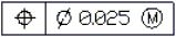
Following is an example of a Tolerance:
The following tables describe the Tolerance and material condition symbols you can select in the Geometric Tolerance dialog box.
| Symbol | Characteristic | Type |
|---|---|---|
 |
Position | Location |
 |
Concentricity or coaxiality | Location |
 |
Symmetry | Location |
 |
Parallelism | Orientation |
 |
Perpendicularity | Orientation |
 |
Angularity | Orientation |
 |
Cylindricity | Form |
 |
Flatness | Form |
 |
Circularity or roundness | Form |
 |
Straightness | Form |
 |
Profile of a surface | Profile |
 |
Profile of a line | Profile |
 |
Circular runout | Runout |
 |
Total runout | Runout |
| Symbol | Definition | Type |
|---|---|---|
 |
At maximum material condition, a feature contains the maximum amount of material stated in the limits. | MMC |
 |
At least material condition, a feature contains the minimum amount of material stated in the limits. | LMC |
 |
Regardless of feature size, indicates that the feature can be any size within the stated limits. | RFS |
To create a Tolerance:
 .
.The Tolerance displays in the graphics area.
Access
Command: Tolerance
Menu: Dimension > Tolerance
Ribbon: Annotate > Dimensions > Tolerance
Related Topics
Creating SmartLeaders
Parent Topic